Making a Drone: Part 2
I managed to get some more time to work on the drone project these past few weeks. One of the first priorities I had was to flash the firmware on the flight controller. I never have used Betaflight before, and I wanted to see what the software looks like and what its capabilites are. The process was fairly straightforward. I downloaded the Betaflight Configurator, which is shipped as a progressive web app (PWA). I’ve never heard of that before, but it’s apparently a web application that can also be downloaded for offline access, which is pretty cool. I downloaded it from https://app.betaflight.com/# and began the process of connecting my flight controller to it.
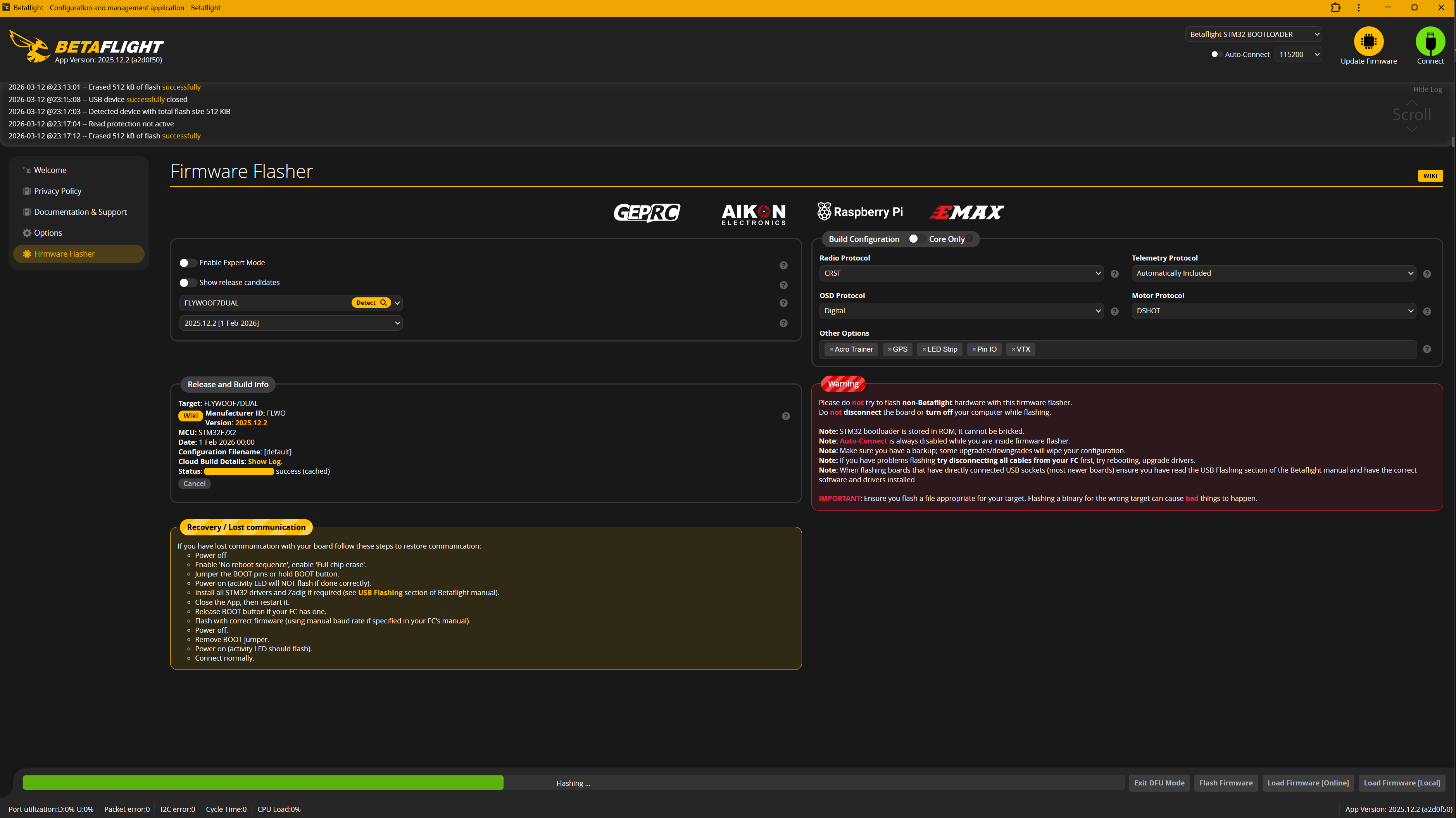
This is where the manual helped me out, as it told me I could get something called Zadig to switch the driver into what is known as “DFU mode,” which is necessary for flashing the firmware. I downloaded Zadig from https://zadig.akeo.ie/ and followed the instructions in the manual to put the flight controller into DFU mode. Once I did that, I was able to select the appropriate firmware for my flight controller and flash it successfully. One hiccup was that, at one point in the instructions, it told me to select the “FLYWOOF7DUAL” platform. I thought that was a bit odd, as there were two options for the Hobbbywing XRotor F7 flight controller, but I thought maybe the two were similar enough that they were cross-compatible. However, after I flashed the firmware, I noticed that I was not able to read the IMUs. Even though I have not attached the flight controller to any external sensors (standalone until I can get the soldering stuff, I discuss more below), I know there are built in IMUs, so I should be able to at least read them. After reviewing the manual again, it turns out they also mention using “HOBBYWING_XROTORF7CONV” in a different section. I switched to that one, and I was finally able to read the internal FC sensors. They should really review their documentation a bit more. Once I connected my flight controller, I was greeted with a screen that looked like the one below.
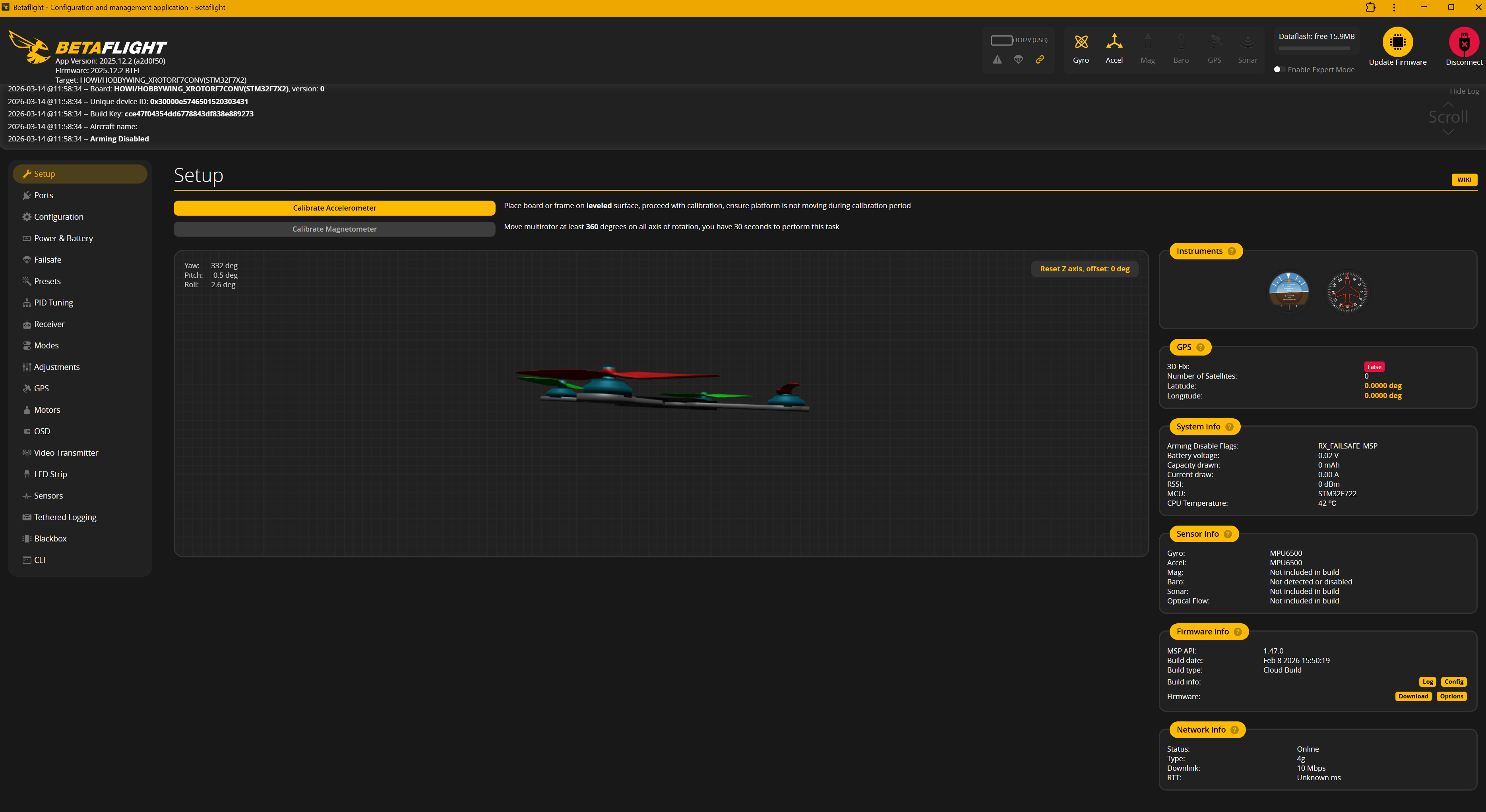
You are able to see that on the top right, I have both gyro and accelerometer data. Even though not everything is finalized, a definite next step is to attach the ESC and solder all the motors to it. The first thing I wanted to do was try to connect the battery to the ESC. The 4in1 ESC had power leads, but they were just waiting for an XT-60 connector. So one task I did was solder an XT-60 connector to those leads. It took me quite a while, as I had trouble getting the solder to adhere properly, even with flux. I don’t solder a lot, so I think my technique might be bad, or I may be using the wrong temperature. Eventually, I managed to attach the leads, wrapping them with some heat shrink tubing. However, after doing so, I realized the FC/ESC stack came with a much better connector, with a plastic covering that can help cover the connection point in addition to heat shrink tubing. I may consider swapping, but this should be good for now. Once I finished attaching it, I wanted to try connecting a 3S battery to the ESC. I figured that since I haven’t messed with the board, it would be a great time to make sure everything was working properly and what everything looks like when connected to power. When I did so, I heard a loud
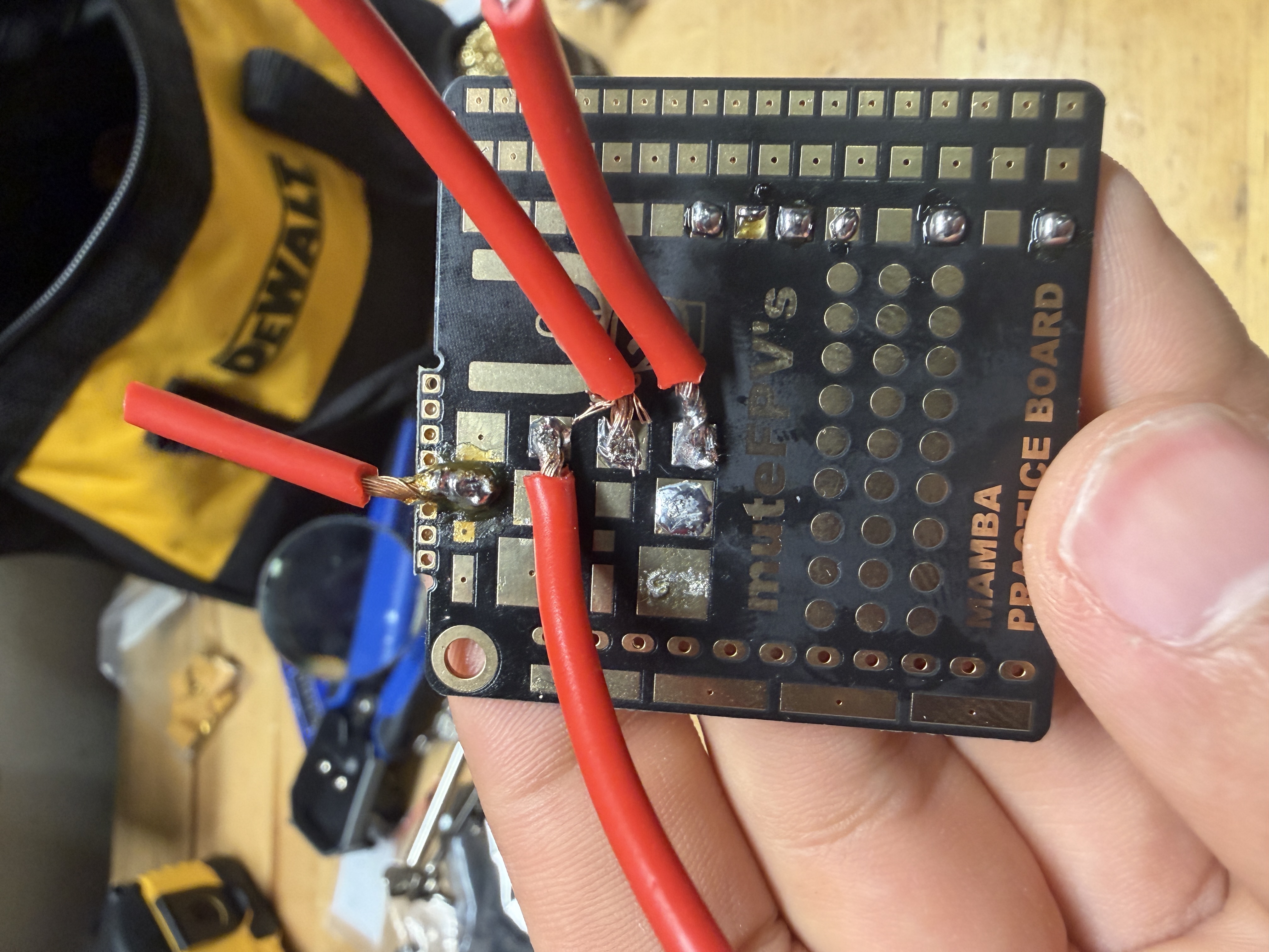
Obviously, these were not great. One issue was that the joints were way too cold. I initially had it at 300C, but I found 450C to be much better. I eventually felt confident enough to try it for real. I experimented with using the solder that came with the practice board and a Weller brand solder that had a flux core. I found that the Weller solder worked much better, and I was able to get a much better joint with it. You can tell the two I used the other solder on, as they are a lot colder, even with the change to 450C. I’m not sure if it was the flux core that made the difference, or something else. You also might notice the solder does not expand across the pad much. I had two big concerns when doing this, which was avoiding bridging and avoiding heating the ESC so high that it damaged the electronics. I think I erred too much on the side of caution, and I could have probably gotten a better joint if I had let the solder flow a little more. I DEFINITELY think it would be good to revisit these again, but these felt like they would hold well enough for a control check. The “final” solder looked like this:
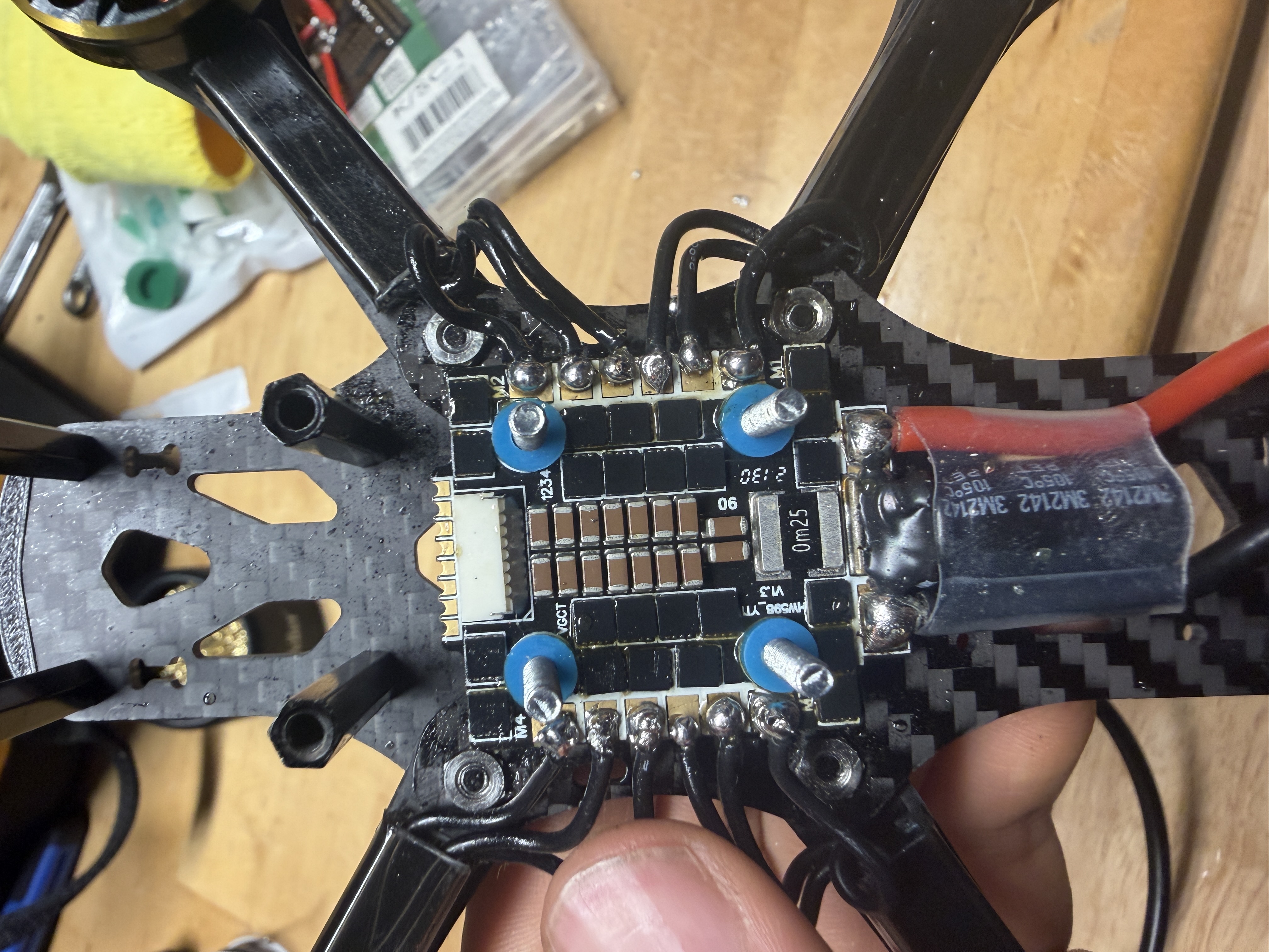
After that, I attached the FC to the ESC, plugged it into the computer, and hooked up a 3S battery through a smoke stopper I got off Amazon. After connecting the battery, the reported voltage was around 12.4, which was a great sign. I went to the motors tab, confirmed I wasn’t going to slice my fingers off (lol), and then started testing the motors. At first, two of them refused to spin, which was a bit concerning. However, after trying to turn the armature by hand, I realized that something was blocking them. Releasing the screws a little bit helped, and I soon had all four of them free. Two of them were turning opposite of the one indicated by Betaflight, so I had to reverse them in the software. After this, I had all four motors spinning together in the correct direction, which was super exciting!
Some final notes for this phase of the project, I have a lot of concern about the height. The 4in1 ESC comes with a capacitor hanging out, that can either stick awkwardly out the side and risk getting damaged, or inside where the FPV box will also need to go. My idea is to have the capacitor face in and put the FPV box above it, strapped to the top plate of the frame, but I am pretty sure I will not have enough room. My idea is to get slightly taller standoffs in order to have enough clearance, but I guess we’ll see. I ordered the DJI O4 Air Unit, which was a bit hard to find, I’m guessing due to recent legislation changes here in the US. I got it off eBay and it should be here in a couple of weeks. I am also still missing some things, including FPV goggles and propellers. Hopefully, I will be able to give you all a better picture of that in the next update, but I am pretty happy with the slow yet steady progress made so far. Until next time!


Leave a comment